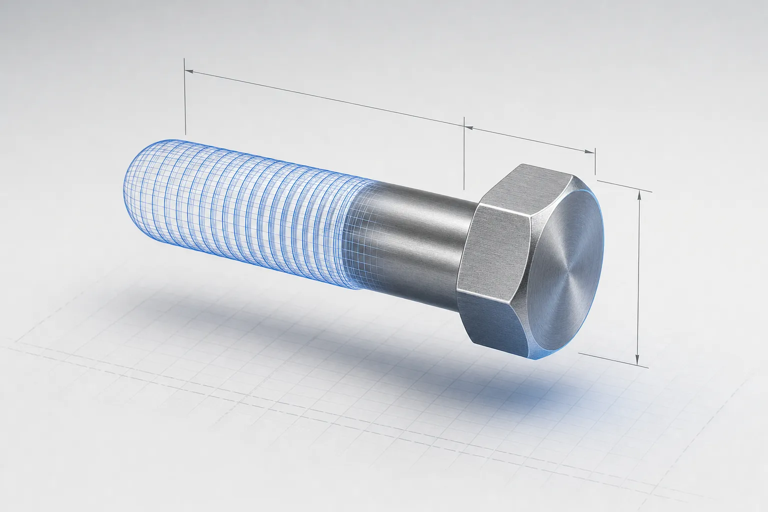
A screw CAD model is useful only when it represents the fastener you intend to specify and contains an appropriate level of detail for the task. Before using a downloaded model, verify its part identity, dimensions, units and thread representation; then consider whether its geometry is suitable for drawings, assembly work, visualisation or another downstream use.
A catalogue download is usually a practical starting point when the required fastener is a defined catalogue item. Parametric generation is worth considering when geometry must change with configuration inputs, or when a product has variants that need to be represented consistently. Neither approach makes the model a substitute for checking the part specification or obtaining engineering approval.
Check the part identity before the geometry
A model can look right while representing a different fastener. Start with the intended part identifier and its governing specification, then compare the model’s available metadata and geometry with the requirements. Check the head style, drive, thread type and size, length, material or grade where relevant, and any other defined options. Not every model file contains all these details, so do not treat a filename or visual match as proof of identity.
Use the identifier as a precise reference, not just a family name. For example, ISO 4017:2022 covers hexagon head screws in steel and stainless steel with metric coarse pitch threads. The standard number alone does not identify a part: the edition, thread size, length and the required property class or stainless steel grade are all needed to distinguish it, and other referenced standards may define material or dimensional options. Consult the applicable product documentation rather than assuming a standard number resolves every choice.
Compare the model against the actual product definition or manufacturer documentation. Depending on the intended use, relevant checks may include overall length, head form and dimensions, drive form, thread extent and any unthreaded portion. If a discrepancy cannot be resolved from the documentation, ask the supplier or responsible engineering team before using the model as a production reference.
For a double-end stud, for instance, a generic screw model is not an adequate substitute for defining the stud’s ends and other required details. See the guide to double-end stud specifications for considerations specific to that product type.
Choose thread detail for the job
A CAD screw may represent its thread as actual helical geometry, as a cosmetic or drawing representation, or with a simplified visual treatment. These approaches are not interchangeable in every workflow. Choose the representation according to what the model needs to communicate and how it will be used.
Modelled helical threads create more geometry than a non-modelled thread representation. SOLIDWORKS publications and Autodesk support both describe performance or file-size costs associated with modelled thread geometry and point to cosmetic threads as an alternative where full geometry is unnecessary. The precise effect depends on the model and software, but highly detailed threads can make files heavier and operations slower.
A cosmetic thread representation can carry drawing-level thread information without modelling the thread’s full helical surfaces. A simplified model can also be appropriate for assembly layout, visualisation or other uses where the thread form itself is not being analysed. However, do not assume that a cosmetic display contains the geometry needed for a particular simulation, manufacturing process or automated check. Confirm what the receiving workflow expects.
Detailed thread geometry may be necessary for a defined purpose, but it should not be included by default merely to make a model look realistic. If a downloaded model has detailed threads, check whether the thread geometry can be suppressed or replaced with a lighter representation while preserving the information needed in the drawing or assembly. The right choice depends on the task, not on a universal rule.
For the drive feature, check that the CAD representation matches the specified drive rather than relying on a similar-looking head. The guide to screw head and drive types explains why those features should be identified explicitly.
Check units, detail and downstream use
Before inserting a downloaded screw 3D model into a design, check its units and scale in the target CAD environment. A file may open successfully yet be interpreted at an unintended scale or with unsuitable units. Compare a known dimension from the part definition with the model in the receiving system, and confirm how the file’s units are handled by the import workflow.
Then consider the model’s level of detail. A representation intended for a catalogue illustration may not include every feature needed for interference checking or manufacturing documentation. Conversely, a model with every thread surface may be unnecessarily complex for a large assembly. File appearance alone does not establish suitability.
Ask what the CAD screw will be used for:
| Intended use | Checks to prioritise |
|---|---|
| Assembly layout or clearance review | Overall envelope, head and shaft form, scale and the features that control fit or interference |
| Drawing or specification communication | Correct part identity and the thread information required by the drawing workflow |
| Visualisation | Recognisable head, drive and proportions, without unnecessary geometric complexity |
| Detailed engineering analysis | Whether the model’s geometry and assumptions are suitable for the particular analysis method |
| Manufacturing or procurement reference | Agreement with the authoritative product definition, not just visual similarity |
These are selection prompts, not guarantees that a model is suitable for every workflow in a row. A model imported into an assembly may need different detail from one used in a drawing, and the receiving CAD system may interpret imported geometry differently. Check the model in its intended environment and document any simplifications that matter to later users.
Catalogue downloads and parametric generation
A standard catalogue model represents a specified item or a limited set of manufacturer-defined variants. A parametric model uses inputs to generate or update geometry. One is not inherently more accurate: the result depends on how the model is defined, the authority of its source information and whether the selected inputs correspond to the intended fastener.
| Consideration | Catalogue download | Parametric generation |
|---|---|---|
| Best suited to | A known catalogue item with a matching model available | A product family whose geometry varies with defined configuration inputs |
| Starting point | A manufacturer or other source’s model for an identified part | Parameters and rules that describe permitted variants |
| Variant handling | Find and verify a separate model for each required item or variant | Inputs can drive geometry for the configured variant, if those inputs and rules are defined |
| Main checks | Part identifier, source, dimensions, units and detail level | Input definitions, permitted combinations, generated geometry and its agreement with product documentation |
| Potential limitation | A visually similar model may not be the exact specified item | A generated result is only as reliable as its underlying definitions and rules |
A parametric model can be useful where a change to an input, such as a defined length or drive option, is intended to affect geometry. Which parameters are available and how they affect the model are product-specific decisions. Do not infer that any input can be changed freely or that a model supports all sizes or combinations.
Illustrative example: a product team could define a screw family with a length input and a choice of drive, then use those inputs to generate the corresponding geometry for a selected variant. This example does not prescribe a universal screw parameter set. The manufacturer’s product definition must determine the available options and the relationships between them.
For a fastener used in a particular material or application, the geometry is only one part of the selection. For example, consult manufacturer guidance and application requirements when choosing a thread-forming screw for plastic; the hole-size guide covers that separate design question.
A practical model-selection checklist
Use this checklist before adopting a downloaded model or approving a generated one:
- Identify the part. Record the applicable manufacturer part identifier or specification, including the variant details needed to distinguish the intended fastener.
- Verify the defining features. Compare relevant dimensions and features with the authoritative product information. Resolve missing or conflicting details rather than guessing from appearance.
- Confirm units and scale. Check the model in the receiving CAD environment against a known dimension.
- Select thread representation deliberately. Decide whether full thread geometry is needed or whether a cosmetic or simplified representation communicates the required information with less geometric complexity.
- Match detail to downstream use. Confirm that the geometry is sufficient for the intended drawing, assembly, visualisation or analysis workflow.
- For a parametric model, review the rules. Establish which inputs are supported, what each input controls and whether the generated variant is checked against product documentation.
- Record the model’s source and status. Make clear whether it is a manufacturer model, an illustrative model or a configured output, and identify any simplifications that could affect later use.
Configuration-specific CAD and CPQ
Manufacturer-defined parameters can support configuration-specific CAD generation when they are translated into clear inputs and rules for the product family. The parameter definitions should reflect the manufacturer’s permitted options and geometry, and the resulting model still needs appropriate engineering review. A configured model does not establish compliance, certify a design or replace physical testing where required.
allpccloud provides web-based CPQ software for technical products, offered as a web service and on-premises. It generates 3D CAD models according to configurable rules and produces a complete product structure at the end of a configuration; fastener-specific rules, calculations, geometry and integrations are implemented per project. The page on parametric fastener configuration describes how this applies to bolts, screws and studs. The screw configurator images shown there come from a demo: example inputs, a 3D preview, detailed or simplified geometry, and generation of a CAD part and an STL file. They are not a guarantee of particular export formats, and allpccloud does not operate a public CAD download library.
For a specific screw family, define the authoritative product data and intended model uses before choosing between downloads and generation. If you would like to discuss how your configuration requirements could be represented, get in touch.
Frequently Asked Questions
How can I tell whether a downloaded screw CAD model is the correct part?
Compare its identifier and defining features with the applicable product specification or manufacturer documentation. Check relevant dimensions, thread, head, drive and material or grade information; appearance alone is not proof of a match.
Should a screw model include fully modelled threads?
Use full helical geometry only when the downstream task needs it. Cosmetic or simplified thread representations can reduce geometric complexity, but confirm that the receiving workflow retains the information it needs.
What should I check about units in a screw 3D model?
Confirm how the file’s units are interpreted by the target CAD system and compare a known dimension with the product definition. A model that opens correctly may still be at an unintended scale.
When is parametric screw CAD useful?
It can help when a product family has defined inputs that drive geometry for permitted variants. The inputs and rules must reflect the manufacturer’s product definition, and each resulting model still needs appropriate review.
Does a generated CAD model certify the fastener design?
No. Model generation does not replace engineering approval, applicable testing or certification. It represents geometry according to its underlying data and rules.