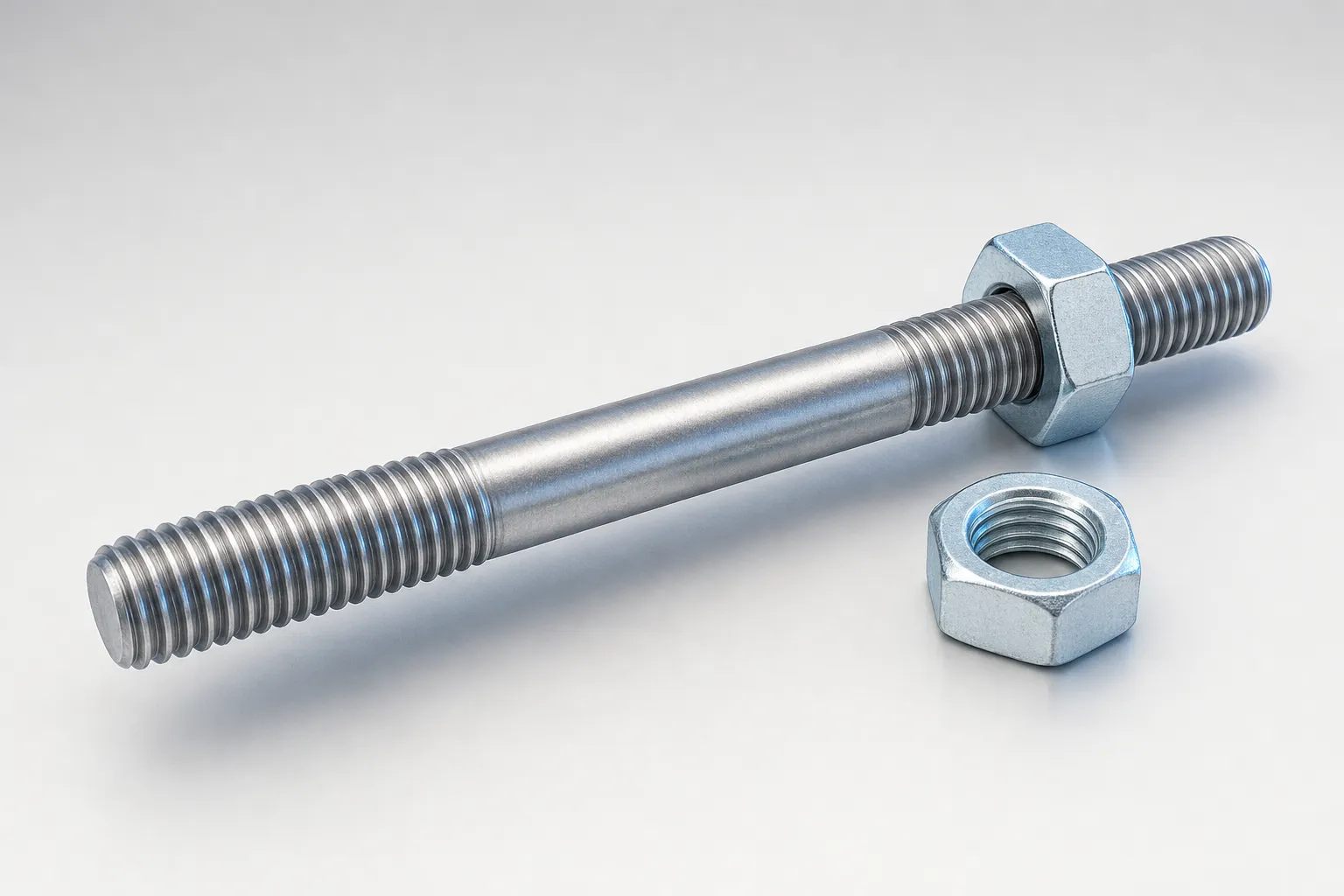
A double-end stud has a threaded section at each end, usually with an unthreaded section between them. To describe one accurately, specify the thread diameter and pitch at each end, the length and function of each threaded section, the overall length, any body geometry, and the required material and finish. If one end is intended to be installed in a tapped component, identify it as the tap or installed end rather than relying on an assumed orientation.
The name alone is not enough to define a product. A quotation or engineering review should make clear whether both ends are alike, how lengths are measured, and which drawing or dimensional convention governs. This matters because double-end studs can be made to different standards or to a customer drawing, and dimensional information in a standard does not establish that a particular product is available from a supplier.
Double-end studs, threaded rods and terminology
A double-end stud is generally a fastener with two threaded ends and a body between them. One end may screw into a tapped hole in a housing or flange, while a nut fits on the other end. In another arrangement, both threaded ends may be alike and nuts clamp two components. Describe the intended arrangement as well as the part name.
A fully threaded rod has threads along its complete length. It does not, by that description alone, identify a distinct installed end, nut end or smooth shank. ASME B18.31.2 covers both continuous-thread studs and double-end studs in its inch-dimensioned scope. It distinguishes a clamping-type double-end stud, with matching thread length and configuration at both ends, from a tap-end type, which usually has different thread lengths. These are distinctions within that standard’s scope, not a universal definition of every product sold as a double threaded stud. See the ASME B18.31.2 scope and contents.
Names such as double end stud bolt and double ended threaded studs are also used in enquiries. Because terminology can vary between suppliers, a drawing or a field-by-field description is safer than relying on the product name alone.
Define both thread ends and the lengths
Treat the two ends as separate specification items, even when they are intended to match. For each end, state the thread system, nominal diameter and pitch. Add any other required thread details, such as the specified tolerance class or fit, from the applicable standard or drawing. If the ends differ, label them consistently, for example as the installed end and the nut end, and state the thread details for each separately.
Do not assume that a single diameter-and-pitch callout describes the whole stud. The end threads can have different specifications, and the installed end may have a different fit from the nut end. The RS Randack article on studs to DIN 938, 939, 835 and 940 describes the metal end as having a tighter fit so that the stud remains in the housing when the nut is loosened. That is a manufacturer explanation of the cited stud arrangement, not a general instruction to apply the same fit to every design. Confirm the required fit with the governing drawing, standard and supplier.
State the threaded length at each end separately. For an installed end, clarify the required engagement length or the length of thread provided, using the terminology and datum on the controlling drawing. For the nut end, define how much thread is available for the nut and any required assembly arrangement. If a length includes a chamfer, run-out or other end feature, make that convention explicit rather than leaving the supplier to interpret it.
Overall length should also have a clear definition: identify the end-to-end measurement and the relevant datum faces. This avoids confusion between total part length, body length and the sum of the threaded lengths. If a standard or drawing already defines the length convention, cite that document and revision rather than creating a competing interpretation.
Specification fields and why they matter
| Field | What to state | Why it matters |
|---|---|---|
| Part identity | Double-end stud, intended arrangement and part number if assigned | Separates a tap-end design from a clamping arrangement or fully threaded rod |
| Governing document | Standard designation or drawing number and revision | Establishes which geometry and requirements control the enquiry |
| End identification | Installed or tap end and nut end, or another unambiguous label | Makes different end specifications and lengths understandable |
| Thread at each end | Thread system, nominal diameter, pitch and any required class or fit | Prevents assumptions that both ends share the same thread |
| Threaded length at each end | Separate length and measurement convention for each end | Defines engagement and usable thread without confusing it with overall length |
| Overall length | End-to-end length, with datum or drawing reference | Distinguishes the total part length from individual thread and body lengths |
| Body geometry | Unthreaded shank, reduced section, collar, spigot, socket or cross-hole as applicable | Captures features that affect fit, manufacture or assembly |
| Material and mechanical requirement | Exact material designation or required property class, as applicable | Gives the supplier a defined basis for material selection and quotation |
| Finish or coating | Required finish, or state that none is specified | Avoids an unstated assumption about surface treatment |
| Quantity and delivery information | Required quantity and requested delivery timing | Enables a relevant commercial response; availability is supplier-specific |
| Inspection and documentation | Required certificates or other deliverables, if applicable | Makes documentation expectations visible before order placement |
This is an enquiry checklist, not a substitute for the controlling product standard or drawing. ASME B18.31.2 includes topics such as body diameter, stud length, ends, thread length, materials and finish within its inch-series scope. Its inclusion of dimensional data does not mean every described configuration is a stock item; the standard advises checking availability with suppliers.
Unthreaded sections and other geometry
If the stud has a smooth shank between the threaded ends, specify its length and diameter where they are controlled by the design. State whether the body is full diameter or reduced, and define any transition, collar or other feature that matters for assembly or clearance. For non-standard parts, a drawing is usually the clearest way to communicate the feature and its datum.
The RS Randack article notes that studs made to drawing may include features such as collars, spigots, hexagon sockets or cross-holes. Treat these as possible drawing-specific features, not standard features of every double-end stud. If the design uses one, show its position and dimensions on the drawing and identify any related requirements.
Where an installed end enters a tapped component, include the housing material or component context when it affects the specified stud arrangement. RS Randack describes the metal-end length for the DIN 938, DIN 939, DIN 835 and DIN 940 family as depending on the housing material. This is a description of that DIN family and its applications, not a universal dimensional rule. Do not select a metal-end length from a general rule of thumb when the design is governed by a particular standard or drawing.
Clear thread identification also helps reduce assembly problems. If the two ends have different purposes, label them on the drawing and in the purchase description. For background on how poor alignment can damage a threaded connection, see the guide to cross-threading causes and prevention.
Material, finish, quantity and revision
Give the required material designation or property class rather than a broad description such as strong steel. The applicable designation depends on the design and governing specification; do not infer it from appearance, application or a supplier’s standard range. If a specific certificate or inspection document is required, name it in the enquiry. The RS Randack enquiry guidance also identifies housing material, nut, coating, certificate type and delivery date as information that may be relevant to a stud enquiry.
State the finish or coating requirement explicitly, including when no finish is specified. A supplier may need to confirm whether a requested finish is available for the selected product and whether it affects the proposed thread details. Do not assume that a finish used on a related fastener is automatically suitable here.
Include quantity and drawing revision with the request. A revision letter or other revision identifier should refer to the drawing actually supplied, not simply the latest file on a shared drive. If the enquiry is for a standard product, state the exact standard designation and any selected options; if it is made to drawing, attach the drawing and identify its revision. For context on how production route and enquiry information can affect fastener definition, see cold-formed fasteners and enquiry requirements.
Common ambiguities that trigger follow-up
Quotation delays often come from details that appear obvious to the designer but are not stated. Examples include a single thread callout with no indication of whether it applies to both ends; an overall length with no datum; or a length that could mean either the threaded portion or the complete end section. Another frequent gap is naming the installed end without specifying its thread length or fit.
Other questions arise when a request says only to supply a stud to a DIN or ASME designation, without identifying the applicable version, size, material or configuration where selection is needed. A supplier may also need to ask whether a collar or unthreaded section is intentional, what finish is required, or whether a certificate is expected. Use the standard or drawing to settle technical definition, then state commercial and documentation requirements separately.
When a design is communicated through CAD, ensure the model and drawing agree on the controlling dimensions and revision. A model may help show shape but should not silently replace a dimensioned specification. See screw CAD models: downloads and parametric generation for related considerations about model use.
Illustrative specification
The following is an illustrative format, not a standard size or recommended design. It intentionally uses named placeholders rather than dimensional values:
| Item | Illustrative entry |
|---|---|
| Part | Double-end stud, installed end plus nut end |
| Governing definition | Customer drawing, revision identified in the enquiry |
| Installed-end thread | Thread system A, diameter D-A, pitch P-A, fit as stated on drawing |
| Nut-end thread | Thread system B, diameter D-B, pitch P-B, fit as stated on drawing |
| Thread lengths | Installed-end length L-A; nut-end length L-B; measurement datums shown on drawing |
| Overall length | Length L-total, measured between the drawing’s defined end datums |
| Body | Unthreaded shank as shown on drawing; any reduced section or feature separately defined |
| Material and finish | Exact designations to be completed from the approved specification |
| Order information | Quantity, required documents and delivery information stated in the enquiry |
If the threads are identical, the specification should say so and still make clear whether the thread lengths match. If they differ, keep the two callouts separate throughout the drawing, bill of materials and quotation request. Avoid relying on a shorthand description that leaves the supplier to infer geometry.
When a configurator can help
A structured fastener configurator can collect the two ends as separate parameter groups, along with overall length, body geometry, material and finish. In allpccloud CPQ, products and parameters can be organised in a browser-based backend, and defined configuration steps can guide a user through selections or dimension inputs. Rule-based estimates, sales documents, 3D CAD models and a complete product structure can be generated where configured for the project. Fastener-specific rules and dimensional checks must be implemented for the relevant project and manufacturer; they are not a universal prebuilt module. Such checks support consistent data capture but do not replace engineering approval, physical testing or certification.
For a specification that needs review against a particular application or drawing, contact allpccloud with the governing information.
Frequently Asked Questions
What is the difference between a double-end stud and a fully threaded rod?
A double-end stud has threaded sections at both ends and may have an unthreaded body between them. A fully threaded rod has threads along its complete length and does not, by that description alone, define an installed end or nut end.
Should the two ends of a double-end stud have the same thread?
Not necessarily. Some arrangements use matching threads at both ends, while a tap-end type may have different thread lengths and can have different end specifications. Identify each end separately in the drawing or enquiry.
How should I specify the length of a double-end stud?
State the overall end-to-end length and define its measurement datums. Also give the threaded length at each end separately, making clear how each length is measured.
Are DIN 938, DIN 939, DIN 835 and DIN 940 interchangeable?
Do not assume they are interchangeable. The cited manufacturer article describes the family in relation to different housing materials and installed-end lengths. Check the governing document and confirm the required product with the supplier.
What information should accompany a quotation request?
Include the governing standard or drawing and revision, both thread specifications and lengths, overall length, body geometry, material, finish and quantity. Add required certificates, delivery information and relevant housing or assembly details.