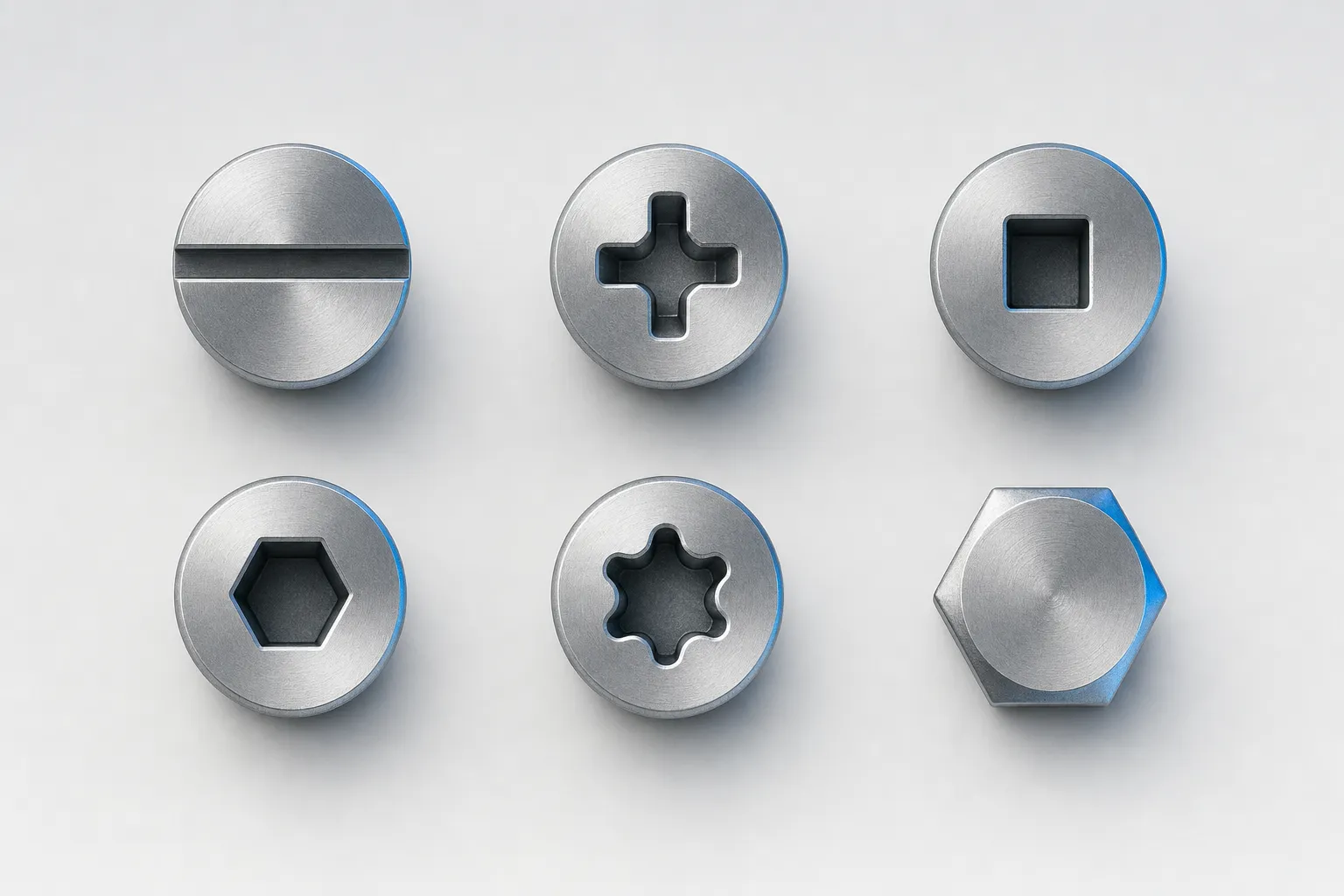
A screw head describes the shape and geometry of the part above the bearing surface; the drive describes the feature engaged by the installation tool. These are separate attributes. A countersunk screw, for example, may have a cross recess or an internal hexalobular drive, while an external hex screw is named for its outside driving flats. To specify a fastener accurately, identify both attributes rather than using a head name as a substitute for a drive description.
The right combination depends on the joint, the available space around the head, the bearing surface, the tool path and the assembly method. Record the head form and drive system separately, then include the relevant dimensions, material, finish and other product requirements in the complete specification.
Head form and drive type are different attributes
Head form describes the fastener’s external shape and the way it meets or sits above the joined component. It affects factors such as the bearing area, available clearance and whether the head is intended to sit proud of or flush with a surface. The drive may be a recess in that head or an external profile around its perimeter.
A useful description therefore combines the two: for example, a pan head with an internal hexalobular drive, or a hexagon flange head with an external hex drive. These are illustrative combinations, not a statement that every manufacturer offers them. A drawing or product specification should establish the exact permitted combination.
Common screw head forms
The table describes common forms in practical terms. Application comments are general engineering considerations; availability, dimensions and exact design details depend on the fastener specification and manufacturer.
| Head form | Geometry and typical consideration | Specification point |
|---|---|---|
| Pan | Rounded top with a relatively broad, flat underside. It normally remains above the component surface. | State the head dimensions and the required drive separately; check that the projecting head will not interfere with neighbouring parts. |
| Countersunk | Tapered underside intended to sit in a matching countersink. | Define the required seating arrangement and verify it against the component geometry. A countersunk head can use different drive types. |
| Button | Low, rounded profile that remains above the surface. | Check the available height and tool access; do not assume that the low profile provides the required clearance. |
| Cylindrical or socket head | Tall, approximately cylindrical head, commonly with a drive recess in its top. | Confirm both the head envelope and the recess. The tool must be able to reach and engage the drive. |
| Hexagon head | External hexagonal form that can be engaged around the outside of the head. | Check socket or spanner access and the surrounding clearance. Bulten notes that a conventional hexagon head has a relatively small bearing surface compared with a hexagon flange head. |
| Hexagon flange head | Hexagonal head with an integral flange beneath it. | The flange provides a larger bearing surface than a conventional hexagon head, as described by Bulten. Check that the flange suits the mating surface and available space. |
Head names alone do not fully define a part. Where the head’s seating or bearing function matters, use a drawing or a recognised product designation and state the necessary dimensions and requirements. Bulten lists external hexagon and hexagon flange head forms against several product standards; those references apply to the described products and should not be treated as a universal specification for every fastener.
Common drive types
A drive can be internal, formed as a recess in the head, or external, formed on the outside of the head or shank end. This distinction affects the tool required and the space needed to reach the fastener. The examples below are not interchangeable categories, and a similar-looking profile does not establish compatibility.
| Drive type | Arrangement | Practical considerations |
|---|---|---|
| Slotted | Straight recess in the head | The tool must align with the slot. Consider whether the tool can be held in position during assembly and whether the slot is accessible. |
| Cross recess, including Ph and Pz | Cross-shaped internal recesses | Specify the required profile rather than writing only “cross-head”. Bulten identifies cam-out risk for cross recess drives; select and verify the driver for the specified system. |
| Internal hexagon | Hexagonal recess | Requires a matching hex key or driver bit and access along the fastener axis. Bulten cites ISO 4762 for a socket-head screw product example; that reference is not a general definition of every internal hex drive. |
| Internal hexalobular, including TORX® | Six-lobed internal profile | Specify the system and size designation given by the fastener manufacturer. ISO 10664 specifies the shape and basic dimensions of the hexalobular internal driving feature and a gauging method; ISO says it is intended for inspection, not as a manufacturing standard. |
| External hexagon | Hexagonal outside profile | An external hex screw needs a suitable socket or spanner around the head, so check radial clearance and access for the tool. |
| External hexalobular, including external TORX® | Lobed external profile engaged by a matching socket | The required socket must match the designated profile and size. Camcar presents external TORX® as an alternative to hex or twelve-point drives and notes a socket-clearance advantage in its comparison; this is product-system information, not a universal clearance rule. |
| Triple square or twelve-point | External multi-point profiles | Bulten notes that these external drives require specific sockets. Name the system explicitly and ensure the matching tool is available. |
| Quadrex® | Proprietary internal recess system | Semblex describes Quadrex® as a licensed engineered recess, not simply a Phillips and square recess combined. Its licensee recommends dedicated Quadrex drivers for best performance. |
TORX® and TORX PLUS® are proprietary systems, not generic names for any lobed recess. EJOT describes T as the designation for internal TORX® profiles and E for external profiles; it describes IP and EP designations for internal and external TORX PLUS® respectively. Follow the manufacturer’s designation and do not infer that similarly shaped drives share a size or tool fit. The same care applies to branded systems such as Quadrex®.
Tool access and assembly considerations
Assess the tool path as well as the fastener. Internal drives generally need access from above or along the fastener axis. External drives need room around the head for the socket or other tool to approach and engage. Nearby walls, recesses, cables and adjacent fasteners can limit access even when the fastener itself fits the joint. Check the actual assembly sequence and intended tool, not just a static view of the head.
Also consider the bearing surface and the assembled surface. A flange head provides a larger bearing surface than a standard hexagon head according to Bulten, but the correct choice still depends on the joint design. A countersunk head calls for a matching seat; a mismatch can affect how the parts meet. These are design checks, not substitutes for the applicable product drawing or engineering approval.
Use the specified driver in good condition and verify engagement in the actual assembly. A profile that looks close may engage poorly, slip or damage the recess or tool. In its product description, EJOT states that the vertical sidewalls of the TORX® profile prevent cam-out, but that manufacturer statement does not establish universal performance for every joint or installation condition. Do not transfer it to other drives or use it as a substitute for assembly validation.
For background on how manufacturing route affects fastener definition and enquiry information, see the guide to cold-formed fasteners. If the fastener is being supplied as a digital component, the guide to screw CAD models explains the distinction between downloads and parametric generation. Assembly engagement and alignment are also relevant to avoiding cross-threading, although drive choice alone cannot prevent it.
How to identify and document the combination
Start with the drawing, product designation or manufacturer’s catalogue entry. Record the head form and drive system as separate fields. If the fastener is already in hand, inspect the recess or external profile and compare it with the manufacturer’s information; appearance alone is not enough to confirm a proprietary drive or its size.
A practical specification checklist is:
- Head form and any relevant head dimensions.
- Internal or external drive, named by its specific system and size designation.
- Required bearing or seating arrangement, including whether the head is intended to sit proud or flush.
- Tool access constraints and the intended assembly tool, where these affect the design.
- Fastener dimensions, material, finish and other requirements from the applicable product specification.
- The source document or drawing revision used to define the selected part.
For example, “illustrative only: pan head, internal hexalobular drive, manufacturer’s stated system and size” is clearer than “round head, star drive”. It avoids implying that all pan heads use the same drive or that every lobed recess has the same tool fit. For procurement or manufacturing, use the exact product designation and drawing rather than relying on a descriptive phrase alone.
Defining permitted combinations in a product range
A manufacturer can define which head-and-drive combinations are permitted for each product family, then require a valid selection rather than allowing every head to be paired with every drive. This makes the available choices clearer for technical sales and helps keep enquiries aligned with the manufacturer’s range. The rules need to reflect actual product and engineering decisions, and any generated specification still requires appropriate review.
For this type of structured selection, screw configuration software can guide users through defined parameters and rules. allpccloud’s web-based CPQ can be configured per project to present product choices and generate a product structure, cost estimates, sales documents or CAD models. Fastener-specific rules and geometry are implemented for each project; software output does not replace testing, engineering approval or certification.
Where a head-and-drive choice affects a live design or assembly process, confirm the combination against the relevant manufacturer documentation and engineering requirements. For help discussing a project-specific configuration, contact allpccloud.
Frequently Asked Questions
What is the difference between a screw head and a screw drive?
The head is the external shape of the fastener where it bears against or sits above the component. The drive is the internal recess or external profile engaged by the installation tool. Specify them as separate attributes.
Can a countersunk screw have different drive types?
Yes. Head form and drive type are separate attributes, so a countersunk head may be offered with different drives. Check the manufacturer’s product information for the actual permitted combinations.
Are TORX® and TORX PLUS® interchangeable?
Do not assume they are interchangeable. They are distinct proprietary systems with their own designations, so specify the system and size stated by the fastener manufacturer and use the matching tool.
How should I specify an external TORX bolt?
Name the external drive system and the manufacturer’s size designation, as well as the head form and relevant fastener dimensions. Confirm the required socket and its access around the head.
Is Quadrex® simply a Phillips and square drive combined?
No. Semblex describes Quadrex® as a proprietary, licensed engineered recess rather than a simple combination of those profiles. Its licensee recommends dedicated Quadrex drivers for best performance.