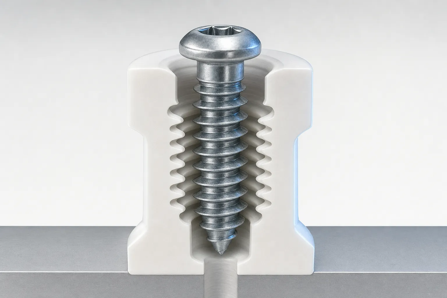
For thread-forming screws for plastic, do not select a hole size from a universal ratio. The appropriate hole depends on the specific screw design, plastic and moulded boss, as well as installation conditions. Start with the screw manufacturer’s recommendation for the exact product and material, then confirm the application with tests.
A useful supplier enquiry includes more than the nominal screw diameter. Provide the plastic grade and processing details, boss dimensions, joint requirements and assembly method. That information helps the supplier recommend a suitable screw and hole, and identifies what needs verification in the part.
Screws for plastic or screws made from plastic?
These are different requirements. Screws for plastic are fasteners designed to form or cut a thread in a plastic component. This guide focuses on those fasteners and the pilot hole in the component. A screw made from plastic is itself a polymer fastener; its material, strength and joining behaviour are separate selection questions. Do not use a recommendation for a screw that fastens into plastic as a specification for a screw made from plastic.
The term “self-tapping” can cover screws that form a thread and screws that cut one. Ask which action the proposed product uses, and request its manufacturer data for the intended substrate. Bossard’s overview also distinguishes thread-forming and thread-cutting screws for plastic.
Thread forming versus thread cutting
A thread-forming screw displaces material in the boss to create the mating thread. It does not remove material in the way a thread-cutting screw does. A cutting screw removes material as it makes the thread. The difference affects the load imposed on the boss and can influence installation, removal and reuse.
| Consideration | Thread-forming screw | Thread-cutting screw |
|---|---|---|
| How the thread is made | Displaces material in the boss | Removes material from the boss |
| Effect during installation | Generates radial and hoop stress in the boss | Leaves lower boss stresses, according to Covestro’s design guide |
| Material guidance | Often considered for suitable thermoplastics; confirm the particular grade and screw | Consider where forming stresses are unsuitable, including materials identified by the manufacturer |
| Reinstallation | Follow product and application guidance | Take care to re-engage the cut thread; Covestro warns that careless reinstallation can damage it |
These are general distinctions, not a rule that one type suits every thermoplastic or that the other suits every thermoset. Covestro advises against thread-forming screws in less compliant materials such as polycarbonate and recommends considering thread-cutting screws there. PENCOM says thermosets are generally too stiff for thread-forming screws, and notes possible trade-offs for cutting screws, including removal and reinstallation difficulty and loosening resistance. Treat these as source-specific material guidance, not a substitute for checking the exact resin, screw and application.
Plastic-specific thread geometry matters too. PENCOM describes screws designed for plastics as typically having narrower, taller threads, sharper flank angles and wider spacing than standard 60-degree thread-forming screws. Its explanation is that this geometry reduces radial force. A standard screw that happens to fit a nominal diameter is not automatically an equivalent choice.
For further background on how manufacturing process affects fastener specifications, see the guide to cold-formed fasteners and enquiry requirements.
Why there is no universal pilot-hole ratio
The pilot hole affects how much material the screw displaces and how the boss responds. The result depends on both sides of the joint: screw details such as thread form and nominal diameter, and substrate details such as polymer type, grade, filler content and moulding condition. Boss geometry and the way the part is installed also matter. A ratio detached from those inputs is not a reliable specification.
Manufacturer recommendations are product-specific. For example, EJOT’s current PT® flyer gives a hole diameter of 0.7 to 0.8 × the nominal screw diameter, depending on the material, and recommends the EJOT DELTA PT® screw for materials with high filler content or high internal strength. This range applies to EJOT PT® screws only; it is not a generic chart for screws for plastics. EJOT’s design recommendations note that deviations may be needed because of processing conditions, mould design, distance from the injection point, flow lines, fillers and differences in material composition, and call for installation tests and a part evaluation when boss geometry changes.
The lesson is not to transfer EJOT’s figures to another product, and to check that you are working from the current edition of a manufacturer’s document. Obtain the current recommendation for the selected screw, material and application. If the manufacturer gives a starting hole or a range, record the product scope and any conditions attached to it.
Boss geometry, engagement and assembly
The pilot hole is only one part of the joint design. Record the boss’s outside dimensions, height, hole depth and entry geometry, together with the available material around the hole. State whether the hole is blind or through, and provide a drawing or CAD model where possible. The dimensions need to describe the actual design being assessed, not an earlier boss revision.
Consider the required thread engagement in relation to the screw length and the parts being clamped. The supplier needs to know how much thread engages in the plastic and whether the screw could bottom in a blind hole. Do not infer a suitable engagement length from the hole diameter alone; ask the screw manufacturer for guidance for the product and application.
Entry features can affect installation. EJOT notes that a counterbore at the boss entry is important for distributing edge stress in its PT® design recommendations. That is manufacturer guidance for the products covered by that document, not a universal requirement for every screw. Ask whether an entry relief or other feature is recommended for the proposed design.
Assembly conditions should be described as well as the component. Include the installation tool and drive, the assembly sequence, and the intended installation speed or control method if known. State whether the screw is installed once or may be removed and reinstalled. The selected drive and installation method should be considered together; the guide to screw head and drive types can help frame that part of the specification. For risks associated with starting the screw incorrectly, see cross-threading causes and prevention.
Information to collect before asking a supplier
A supplier can make a more useful recommendation when the enquiry describes the complete joint rather than asking only for a pilot-hole diameter. Gather the following information and identify anything that is not yet known.
| Information to provide | Useful detail | Why it matters |
|---|---|---|
| Plastic substrate | Resin name and grade, thermoplastic or thermoset, filler or reinforcement, and known material variation | Material behaviour affects whether forming or cutting is appropriate and can affect the recommended hole |
| Part and process | Moulded or otherwise processed part; relevant processing or moulding details available | The manufacturer may need processing information to assess variation in the boss material |
| Screw proposal | Manufacturer, product family, nominal diameter, length, material or finish, and thread-forming or thread-cutting action | Recommendations are tied to a specific screw design and product scope |
| Boss and hole | Drawing or model; boss outside dimensions and height; hole depth, entry shape and whether blind or through | Geometry affects the available material and the joint the supplier is being asked to assess |
| Joint and engagement | Parts being joined, clamped stack, required engagement and any risk of the screw bottoming | Shows how the screw interacts with the full assembly, not just the plastic boss |
| Assembly method | Tool and drive, sequence, installation control, and any removal or reuse requirement | Helps assess installation behaviour and the risk of damage or incorrect engagement |
| Service and acceptance needs | What the joint must do, relevant operating conditions, and how success will be evaluated | Lets the supplier and engineering team agree what the application test needs to check |
| Design status | Current revision, known changes to boss geometry, and whether the part is production-representative | Makes clear which design the recommendation and any test results apply to |
If a resin grade or process detail is unavailable, say so rather than substituting a generic description such as “plastic”. Ask the supplier which missing inputs prevent a product-specific recommendation and whether the proposed screw is intended for forming or cutting in that material.
Confirm the recommendation in the application
Treat manufacturer data as a starting point for the defined product and conditions. Test the screw in a representative part using the intended assembly process. The evaluation should address the needs of the joint, such as whether installation is consistent, the boss remains acceptable and the assembled connection meets its requirements. Agree suitable test methods and acceptance criteria with the responsible engineering team and supplier; this guide does not prescribe universal values.
Reassess the application if the screw, resin grade, material composition, boss geometry or process changes. EJOT specifically calls for a part evaluation when boss geometry is changed. More generally, a recommendation or test on one design does not automatically establish suitability for a revised design.
Representing the selection in a guided workflow
Once engineering has approved the selection rules, required inputs and applicable product recommendations, they can be represented in a rule-based fastener configuration. A guided workflow could collect the agreed substrate and geometry inputs, direct users to eligible screw options and flag missing information for review. Product-specific rules and calculations would need to be implemented for the project; a configured result does not replace application testing, engineering approval or certification.
For help discussing how engineering information could be structured for a fastener selection process, contact allpccloud.
Frequently Asked Questions
Can I use one pilot-hole ratio for all screws for plastic?
No. Hole selection depends on the particular screw, plastic, boss geometry and assembly conditions. Use the manufacturer’s recommendation for the exact product and verify it in the application.
Are thread-forming and thread-cutting screws interchangeable?
No. Forming screws displace material and create stresses in the boss, while cutting screws remove material. Suitability depends on the screw design and substrate, so confirm the choice with the manufacturer.
Does EJOT’s 0.7 to 0.8 × d range apply to all plastic screws?
No. EJOT gives that material-dependent range for its own PT® screws only. EJOT also notes that material and processing conditions can require deviations and recommends installation tests.
What information should I send a fastener supplier?
Provide the plastic grade and composition, proposed screw and product family, boss and hole geometry, joint and engagement details, and assembly method. Include the design revision and any reuse or service requirements.
When should a pilot-hole recommendation be tested again?
Test in a representative application and reassess after changes to the screw, plastic, boss geometry or process. A recommendation for one design should not be assumed to cover a revised design.